iPlace Architecture
iPlace consists of two main modules:
• The web interface
• The core

The web interface is responsible for managing the interaction with the user. Through it you can configure the system behavior and monitor the different system devices in real time.
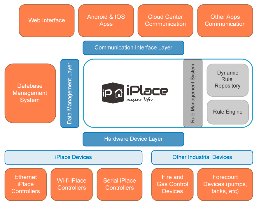
As for the iPlace core, the following figure details its architecture:

As can be seen in the figure, the iPlace core presents a centralized architecture, where integration with the different elements involved is done through three main layers.This allows all the information to pass through the central core, making it possible to process it in real time.
To carry out the decision making, the core has a rule management system, which uses the information received from the different subsystems to carry out the different actions.
Con el fin de facilitar su comprensión, a continuación se describe por capas la figura arriba expuesta.
In order to facilitate its understanding, the figure above is described by layers below.
Hardware Devices Layer (HDL)
It is the layer that allows iPlace to abstract from the peculiarities of the different hardware devices that are going to communicate with it. Any device or hardware sensor can be easily integrated by creating a controller (iPlace Driver) that implements the communication protocol used by that terminal. In this way, iPlace already has drivers developed to communicate with proprietary devices, such as fire and gas power plants, electric meters, devices located in a service station (pumps, tanks, etc.). In addition, iPlace has a wide range of proprietary hardware devices called iPlace Controllers. There are several types depending on the type of connection they use:- Serial: are devices that are connected to iPlace through a serial connection.
- Ethernet: in this case the connection is through a local wired network.
- Wi-Fi: also connected within a local network, but they do it wirelessly. They can be powered by a battery or the electricity grid.
- Optimize the communication protocol with by sending a reduced frame relay and only when an event occurs.
- Parameterize refresh times, sensor sensitivity, etc.
- In the case of Ethernet devices, they have the ability to find devices in the network in a completely transparent for the IP protocol.
Data Management Layer (DML)
This layer implements communication with the database management system. In this sense, the coupling between the iPlace and the data manager has been considerably reduced.In this way, any change in the database server could be easily remedied not compromising the kernel. It would be enough to reconfigure the DML layer to make it work with the new version of the software.Communication Interface Layer (CIL)
If the HDL is responsible for receiving data from the sensors and acting upon hardware devices, this layer is responsible of sending information to other high-level systems: – Web interface: is the iPlace web interface which, apart from allowing the configuration of the platform, offers the possibility of real-time monitoring of all devices that are integrated into the system. In addition, it is possible to execute actions to change the state of the hardware actuators. – Android and iOS Apps: iPlace has mobile applications to monitor and act in real time. Receiving notifications and events of interest, etc. – Cloud Center Communication: It is a platform in the cloud that allows the integration of several iPlaces. In this way, all the data received by each one of the facilities are sent to this central platform, where the data are processed and stored for further consultations. Through this Cloud Center, the user can interact with all iPlaces he has access to and monitor the values in real time. – Other apps: thanks to the CIL layer, it is very easy to integrate third-party applications with iPlace. In this way, any system that wishes to receive data related to the devices managed by iPlace will be able to do so through the implementation of its communication API. The system can be installed on any machine that has one of the supported operating systems. It will be necessary that this equipment is connected to the network so that the user can access the web interface.Information
